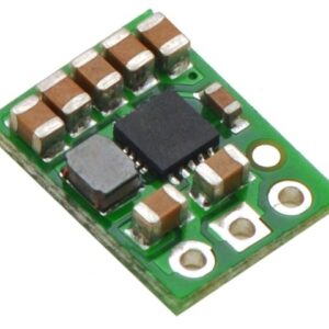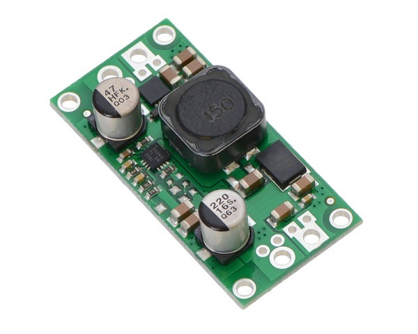
These step-up/step-down regulators take an input voltage from 3 V to 30 V and increase or decrease it as necessary to produce a fixed 5 V, 6 V, 9 V, or 12 V output, depending on the version. They are switching regulators (also called switched-mode power supplies (SMPS) or DC-to-DC converters) with a single-ended primary-inductor converter (SEPIC) topology, and they have a typical efficiency between 80% and 90%. The available output current is a function of the input voltage, output voltage, and efficiency (see the Typical Efficiency and Output Current section below), but it will be around 2 A when the input voltage is close to the output voltage.
The flexibility in input voltage offered by these regulators is especially well-suited for battery-powered applications in which the battery voltage begins above the desired output voltage and drops below the target as the battery discharges. Without the typical restriction on the battery voltage staying above the required voltage throughout its life, new battery packs and form factors can be considered. For example:
The no-load quiescent will typically be between 1 mA and 5 mA for all possible combinations of input and output voltages (e.g. the quiescent current of the 12 V version is approximately 4 mA with 3 V in, 1.5 mA with 12 V in, and 1 mA with 30 V in). The ENABLE pin can be used to put the board in a low-power state that reduces the quiescent current to between 10 and 20 µA per volt on VIN (e.g. approximately 30 µA with 3 V in and 500 µA with 30 V in).
This regulator has built-in reverse-voltage protection, over-current protection, thermal shutdown (which typically activates at 165°C), and an under-voltage lockout that causes the regulator to turn off when the input voltage is below 2.5 V (typical).
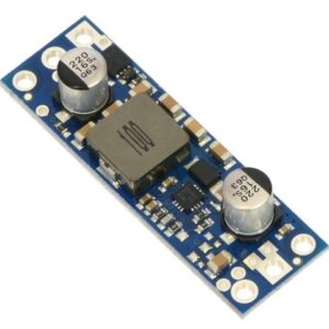
For similarly powerful boost-only regulators, consider our U3V50x regulator family, which are typically more appropriate if you know that your input voltage will always be lower than your output voltage.
1 32 V is the absolute maximum operating voltage; the recommended maximum operating voltage is 30 V, which is the limit of the reverse voltage protection.
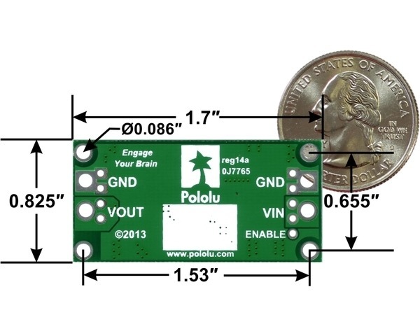
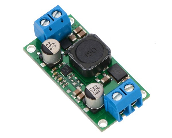
This step-up/step-down regulator has four connections: input voltage (VIN), ground (GND), and output voltage (VOUT), and ENABLE.
 |
The input voltage, VIN, should be between 2.9 V and 32 V. Lower input voltages can cause the regulator to shut down or behave erratically; higher input voltages can destroy the regulator, so you should ensure that noise on the input is not excessive. 32 V should be treated as the absolute maximum input voltage. Our recommended maximum operating voltage is 30 V, which is the limit of the reverse voltage protection.
The regulator is enabled by default: a 100 kΩ pull-up resistor on the board connects the ENABLE pin to reverse-protected VIN. The ENABLE pin can be driven low (under 0.7 V) to put the board into a low-power state. The quiescent current draw in this sleep mode is dominated by the current in the pull-up resistor from ENABLE to VIN and by the reverse-voltage protection circuit, which will draw between 10 µA and 20 µA per volt on VIN when ENABLE is held low (e.g. approximately 30 µA with 3 V in and 500 µA with 30 V in). If you do not need this feature, you should leave the ENABLE pin disconnected. Note that the SEPIC topology has an inherent capacitor from input to output; therefore, the output is not completely disconnected from the input even when the regulator is shut down.
|
|
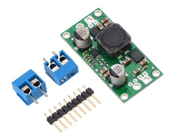
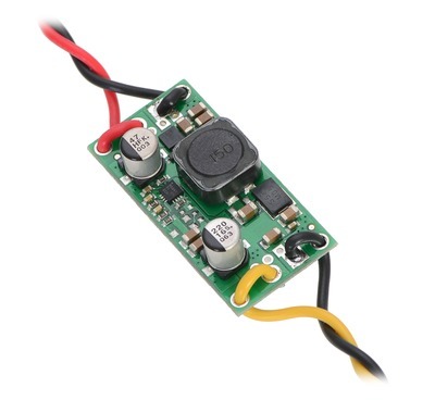
The connections are labeled on the back side of the PCB, and the board offers several options for making electrical connections. You can solder the included 2-pin 5mm-pitch terminal blocks to the two pairs of larger holes on the ends of the board. Alternatively, if you want to use this regulator with a solderless breadboard, 0.1″-pitch connectors, or other prototyping arrangements that use a 0.1″grid, you can solder pieces of the included 9×1 straight male header strip to the 0.1″-spaced smaller holes (each large through-hole has a corresponding pair of these smaller holes). For the most compact installation, you can solder wires directly to the board.
  |
The board has four 0.086″ mounting holes intended for #2 or M2 screws. In applications where mounting screws are not used and wires are soldered directly to the board, the insulated part of the wires can be passed through the mounting holes for strain relief. The picture above shows an example of this with 20 AWG wire, which was close to the limit of what would fit through the mounting holes.
The efficiency of a voltage regulator, defined as (Power out)/(Power in), is an important measure of its performance, especially when battery life or heat are concerns. As shown in the graphs below, these switching regulators have an efficiency of 80% to 90% for most combinations of input voltage, output voltage, and load.
|
The maximum achievable output current of the board varies with the input voltage but also depends on other factors, including the ambient temperature, air flow, and heat sinking. The graphs below show output currents at which this voltage regulator’s over-temperature protection typically kicks in after a few seconds. These currents represent the limit of the regulator’s capability and cannot be sustained for long periods, so the continuous currents that the regulator can provide are typically several hundred milliamps lower.
  |